Pre-Start Checklist for Plate Heat Exchanger Installation
A practical pre-start checklist for plate heat exchanger installation covers mechanical integrity, fluid compatibility, flow direction, and controls. Verifying these setup items before startup reduces operational errors and supports safe PHE commissioning.
- Verify mechanical integrity, gasket condition, and flow direction before energizing a unit.
- Match fluid compatibility, pressure ratings, and temperature limits to the operating process.
- Confirm controls, alarms, and instrumentation reflect the intended operating sequence.
- Document setup checks and deviations to create a reliable baseline for commissioning.
- Treat any mismatch between the datasheet and the installed configuration as a stop-work item.
Why pre-start checks matter
A plate heat exchanger installation is not complete when the last bolt is tightened. The unit must also be verified against the process, the controls, and the operating sequence. Most early operational errors trace back to a setup item that was overlooked during handover.
The pre-start phase is the last chance to catch a mismatch before the heat exchanger is exposed to pressure, temperature, or flow. A single reversed flow path, an incorrect gasket type, or an unverified control setting can cause poor performance, fouling, or damage.
This checklist groups the verification steps by theme. Each item includes the reason for the check and the red flags that indicate a problem.
Confirm the mechanical assembly
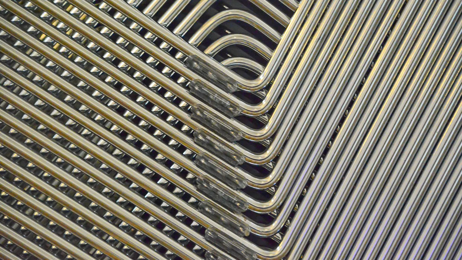
Start with the physical unit. A plate heat exchanger is a stack of plates held between end plates, with gaskets and connecting hardware securing the assembly. The mechanical integrity of this stack determines whether the unit can hold pressure and maintain flow distribution.
- Verify the plate count and order. The installed stack should match the purchased configuration. A missing or extra plate changes the surface area and can shift the pressure drop.
- Check the gasket material and condition. Gaskets must match the fluid, temperature, and pressure service. Look for tearing, compression set, or chemical swelling.
- Inspect the end plates and channel edges. The channel edges should be clean and free of nicks that could cut the gasket.
- Confirm the bolt torque sequence. Uneven torque can distort the end plates and create leakage paths or uneven pressure distribution.
- Verify the support and orientation. The unit should sit on the intended supports and not be stressed by piping.
- Check the drain and vent points. These should be open and unobstructed before startup.
Red flags include visible plate deformation, gasket displacement, bolted joints that look uneven, or piping that pulls on the exchanger body.
Verify the fluid compatibility
Fluid compatibility is a direct safety and performance check. The plates, gaskets, and seals must be rated for the specific fluids, including any cleaning agents or startup fluids.
- Match the gasket material to the hot and cold side fluids. A gasket rated for water service may not survive steam, solvents, or high-temperature oil.
- Confirm the plate material is compatible with the fluids. For aggressive or corrosive processes, the plate alloy and any coatings must be verified.
- Check the seals on the ports and connections. O-rings and packing must match the fluid and temperature.
- Verify the cleaning protocol. If the process involves CIP or chemical cleaning, the gaskets and seals must be rated for that chemistry.
- Confirm the startup fluid. If the unit is flushed with a different fluid than the normal operating fluid, the seals must tolerate that fluid for the flush duration.
Red flags include gasket color changes, swelling, or a chemical odor. If the gasket material is not documented, do not assume compatibility.
Check the pressure and temperature ratings
The installed unit must match the process design conditions. A plate heat exchanger is not a generic part. It is selected for a specific pressure, temperature, and flow envelope.
- Verify the maximum allowable working pressure for each side. The cold side and hot side may have different ratings.
- Confirm the maximum operating temperature for each side. The plates and gaskets have different temperature limits.
- Check the design flow rate. The installed piping and valves must allow the intended flow without causing excessive pressure drop.
- Verify the pressure relief protection. If the process can exceed the rated pressure, the relief path must be functional.
- Confirm the thermal expansion allowance. The piping and supports must accommodate thermal movement.
Red flags include a mismatch between the nameplate and the process datasheet, missing relief valves, or piping that shows signs of thermal stress.
Confirm flow direction and bypass
Flow direction is one of the most common installation errors. The plates are designed for a specific flow path, and reversing the flow can reduce efficiency and cause uneven wear.
- Identify the hot inlet, hot outlet, cold inlet, and cold outlet ports.
- Verify the flow direction against the datasheet or the vendor’s installation drawing.
- Check the bypass valves. A closed bypass during normal operation is required for full flow through the plates.
- Confirm the pump orientation. If the pump is installed to push fluid through the exchanger, the impeller and casing must be rated for the exchanger’s pressure drop.
- Verify the flow indicators. If flow meters or direction indicators are installed, they should show the correct direction after startup.
Red flags include reversed flow on a directional indicator, a bypass that is open during normal operation, or a pump that cannot overcome the exchanger’s pressure drop.
Setup verification for controls and instrumentation
The controls must reflect the intended operating sequence. A plate heat exchanger is often part of a larger process, and the startup sequence must be coordinated with the pumps, valves, and heat sources.
- Verify the control mode. The exchanger may be controlled by temperature, pressure, or flow. The control system must be set to the correct mode.
- Check the alarm limits. The alarms should reflect the safe operating envelope. For example, a high-temperature alarm should trigger before the gasket limit.
- Confirm the interlocks. If the pump cannot start without flow, or if the heat source cannot start without cooling, the interlocks must be functional.
- Verify the instrumentation calibration. Temperature sensors, pressure gauges, and flow meters should be calibrated and within tolerance.
- Check the control valve position. The control valve should be open enough to allow the initial flow, but not so open that it bypasses the intended control logic.
Red flags include alarms that are disabled, interlocks that are bypassed, or instruments that do not respond to changes in flow or temperature.
Documentation and handover
The final step is to create a record of the pre-start verification. This document becomes the baseline for commissioning and future maintenance.
- Record the plate count and order.
- Record the gasket material and seal type.
- Record the pressure and temperature ratings.
- Record the flow direction and bypass status.
- Record the control settings and alarm limits.
- Record any deviations from the datasheet.
Red flags include missing documents, unverified assumptions, or a handover that does not include a clear operating procedure.
Red flag table
The table below summarizes the most common pre-start errors and the action required.
| Item | Red flag | Action |
|---|---|---|
| Gasket material | Swelling or color change | Replace the gasket and verify chemical compatibility |
| Flow direction | Reversed flow on indicator | Reverse the piping or correct the pump orientation |
| Pressure rating | Nameplate lower than process design | Stop and verify the unit or reduce process conditions |
| Bypass valve | Open during normal operation | Close the bypass and verify the flow path |
| Control alarm | Disabled or set above limit | Enable the alarm and set it to the safe operating limit |
Final verification
Before turning on the heat exchanger, walk the unit one last time. Confirm that the piping is secure, the valves are in the correct position, and the controls are armed. Start the unit at a low flow rate and monitor the pressure, temperature, and flow. If the values are within the expected range, increase the flow to the normal operating rate.
The pre-start checklist is a practical tool for preventing operational errors. It is not a substitute for the vendor’s installation instructions, but it is a useful supplement. When the unit is installed correctly, the heat exchanger will perform as expected. When the unit is not verified, the errors will show up quickly, and the cost of correction will be higher.
Frequently asked questions
What is the most common error in plate heat exchanger installation?
Reversed flow direction is one of the most common errors. It reduces efficiency and can cause uneven wear. Verify the flow path against the datasheet before startup.
How do I verify the gasket compatibility?
Match the gasket material to the fluid, temperature, and pressure service. Check the vendor's gasket compatibility chart and confirm the gasket is not damaged or chemically degraded.
Can I start the unit without checking the bypass valve?
No. A bypass valve that is open during normal operation will reduce the flow through the plates and lower the heat transfer efficiency. Close the bypass and verify the flow path.
What should I do if the pressure rating does not match the process?
Stop the installation and verify the unit. If the unit is not rated for the process, replace it or reduce the process conditions to a safe level.
How long should the pre-start verification take?
The time depends on the complexity of the process. A simple water-to-water application may take a few hours. A high-temperature or high-pressure application may take a full day. Do not rush the verification.